To design a solar panel layout, start by reading the roof planes and their orientation, then fill each usable plane with modules while holding fire-access setbacks and clearing every obstruction. Point arrays as close to true south (azimuth ~180 deg) as the roof allows for the most annual output in the northern hemisphere, and keep the module count inside the voltage and current window of the inverter you plan to use. A common fire-access rule is a roughly 3 ft pathway near the ridge, though your local authority sets the exact figure.
Key takeaways
- Read the roof planes first: orientation, tilt, and usable area drive everything else.
- South-facing (azimuth ~180 deg) gives the most output; east and west cost some production.
- Hold fire-access pathways and setbacks, and design for NEC rapid shutdown from the start.
- Match the module count to the inverter's voltage and current window before you commit.
- Sketch fast in PVSketch, then push the design into PVCAD for a permit-ready plan set.
- Read the roof before you draw a single module
- Set azimuth and tilt for the actual site
- Hold fire-access pathways and setbacks
- Clear obstructions and keep working offsets
- Space rows so the array does not shade itself
- Match the module count to the inverter
- What each roof orientation costs you
- A pre-layout checklist you can run every time
- Where rooftop layouts go wrong
- From a fast sketch to a permit-ready set
Read the roof before you draw a single module
Every good layout starts with the roof, not the panels. Before you place anything, break the roof into its separate planes and note how each one faces and how steep it sits. A simple gable has two planes. A hip roof or a cut-up suburban home can have six or more, and each plane behaves like its own small power plant with its own orientation.
Pull the usable dimensions of each plane. Measure eave to ridge, and rake to rake. Note the ridge line, the valleys, and any plane that faces a bad direction so you can rule it out early. The goal here is to know, before you draw, which planes are worth filling and which ones you will skip.
Get the module dimensions in hand too. A standard 60-cell or 66-cell residential module is close to 3.3 ft by 5.5 ft, so a plane that reads 20 ft wide holds about six modules across in portrait. Doing this math up front tells you the realistic ceiling for each plane and keeps you from promising a system size the roof cannot hold.
Decide module orientation per plane while you are at it. Portrait usually packs a narrow, tall plane better, and landscape can win on a wide, short plane. Try both quickly on your two or three best planes before you settle, because a single orientation flip can add or drop a full row of modules. Note the roofing material too, since tile and standing-seam metal change how the racking attaches and how much edge you realistically keep.
Set azimuth and tilt for the actual site
Azimuth is the compass direction a plane faces, and it drives production more than almost any other single choice. In the northern hemisphere, a plane pointed at true south (azimuth ~180 deg) collects the most energy over a year. As you rotate toward east or west you give up some of that output, and a north-facing plane gives up a lot.
The U.S. Department of Energy notes that a south-facing orientation captures the most sunlight over the course of a year in the northern hemisphere, with east and west facing surfaces producing less (DOE, Solar Performance and Efficiency). That does not mean you refuse every east or west roof. It means you know the tradeoff before you sell it.
Tilt is the pitch of the plane off horizontal. On a pitched roof you usually take whatever the roof gives you, often somewhere near 18 to 30 degrees. On a flat roof you add racking to tilt the modules up, which then forces a row-spacing decision I cover below. Do not treat any single tilt or azimuth as a fixed production number. Real output depends on irradiance, tilt, shading, temperature, and system losses together, so model the plane rather than trusting a rule of thumb (DOE).
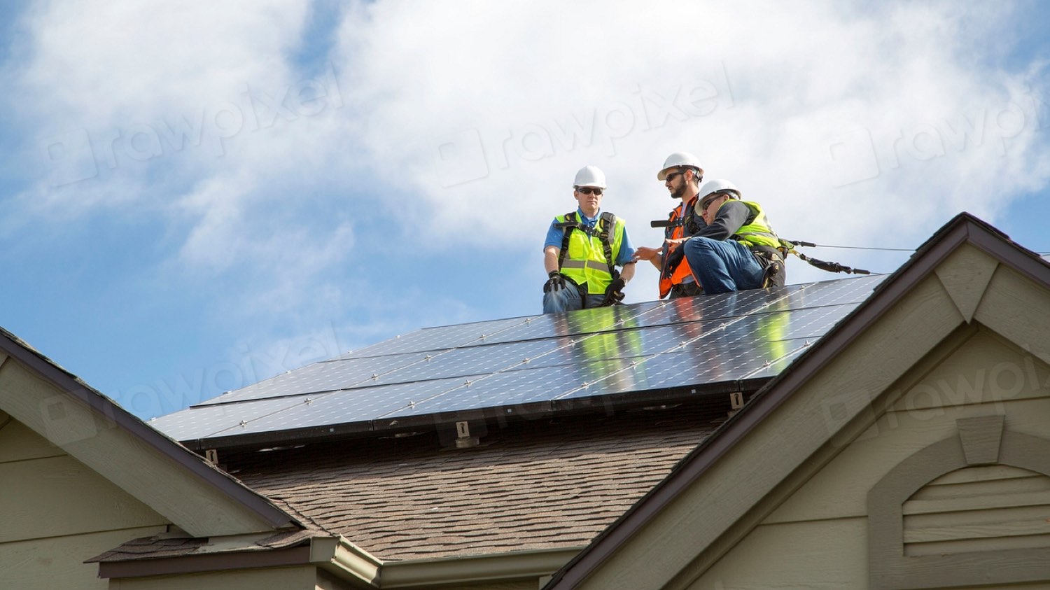
Hold fire-access pathways and setbacks
Firefighters need room to move on a roof and a clear path to vent it. That is why rooftop arrays leave access pathways and edge setbacks instead of covering every square foot. A pathway near the ridge of roughly 3 ft is common, but the exact width, and which edges need clearance, come from your local fire code and the authority having jurisdiction. Confirm the numbers for your jurisdiction before you draw the array boundary.
The electrical side is just as strict. Rooftop PV has to meet the National Electrical Code, including rapid-shutdown requirements in NEC Article 690 that let responders de-energize conductors on the roof. The National Fire Protection Association describes the NEC as the benchmark for safe electrical design and installation (NFPA, Understanding NFPA 70).
The NFPA presents NFPA 70, the National Electrical Code, as the widely adopted benchmark for the safe installation of electrical wiring and equipment, which is the framework rooftop PV layouts have to design around.
NFPA 70 (National Electrical Code)
Draw the setbacks as real boundaries on the plane first. Then place modules inside that shrunken box. Designers who fill the plane and subtract pathways afterward almost always lose modules and have to redraw.
Clear obstructions and keep working offsets
Roofs are cluttered. Plumbing vents, exhaust fans, skylights, chimneys, dormers, and satellite mounts all sit in the way, and each one needs clearance so the array can be installed and serviced. Walk the roof or the imagery and mark every penetration before you place a module.
Two things matter with an obstruction: the physical space it takes, and the shadow it throws. A vent pipe near the south edge of a plane can shade cells for part of the day, and one shaded cell can drag down a whole string. Give obstructions a working offset so you can flash and maintain them, and keep taller objects far enough north that their midday shadow misses the array.
When a plane is broken up by obstructions, do not force a single rigid block of modules. Split the array into smaller sub-arrays that each fit cleanly between the clutter. A layout that respects the real roof beats one that looks tidy on paper but cannot be installed.
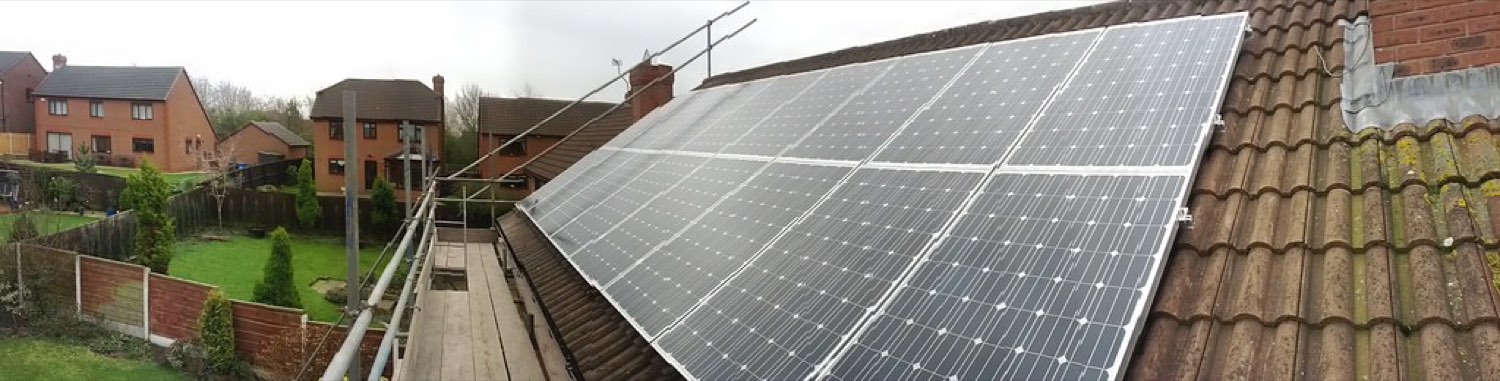
Space rows so the array does not shade itself
Row spacing only matters when modules are tilted up off the surface, which happens on flat commercial roofs and on ground mounts. Flush-mounted modules on a pitched roof share the same plane, so they do not shade each other and you can pack them tight.
On a tilted array, each row casts a shadow to the north, and if the next row sits in that shadow you lose winter morning and evening production. The fix is inter-row spacing sized to the worst-case sun angle you care about, usually near the winter solstice. Tighter spacing fits more modules but increases self-shading. Wider spacing cuts shading but uses more roof. That balance is the ground coverage ratio, and it is a design decision, not a fixed rule.
A practical starting point on a low-tilt flat roof is a row-to-row pitch of roughly two to three times the module's vertical rise, then tune it against a shading model for your latitude. Higher tilt and higher latitude both push that spacing wider. Treat any starting ratio as an estimate and confirm it with real shading numbers for the site.
Match the module count to the inverter
A layout is not done when the modules fit the roof. It is done when the electrical design fits too. String inverters have a maximum input voltage and a usable MPPT window, and the number of modules in a string has to keep voltage inside that window across the full temperature range of the site.
Two limits set the string length. Cold mornings push module voltage up, so the string has to stay under the inverter's maximum voltage on the coldest expected day. Hot afternoons push voltage down, so the string has to stay above the minimum MPPT voltage on the hottest day. Size the string for both ends, then confirm the total array current and power stay within the inverter's ratings.
Module-level electronics change the math. Microinverters and DC optimizers handle mismatch per module, which gives you more freedom to mix orientations and split arrays across planes. Whatever you pick, decide it while you are still laying out modules, because the electrical limits often trim or reshape the array you first sketched.
Watch the DC-to-AC ratio while you are here. Loading more module power behind an inverter than its AC rating, often somewhere near a 1.1 to 1.3 ratio, is normal and can lift energy on cloudy days, but push it too far and you clip peak production. The right ratio depends on the site and the equipment, so model it rather than defaulting to a single number. When the count that fits the roof and the count the inverter wants disagree, that gap is your real design constraint, and it is far cheaper to resolve it now than after the plan set is drawn.
What each roof orientation costs you
This table gives rough relative annual output for a fixed, unshaded plane in the northern hemisphere, plus where each orientation earns its place. Treat the percentages as planning estimates and model the real site before you quote a number.
| Orientation | Approx. azimuth | Relative annual output (est.) | Best use | Watch for |
|---|---|---|---|---|
| Due south | ~180 deg | Highest, baseline | Maximum annual energy | Peaky midday production |
| Southeast / southwest | ~135 / ~225 deg | Slightly below baseline | Strong all-around choice | Small seasonal skew |
| Due east | ~90 deg | Noticeably lower | Morning-heavy loads | Weak afternoon output |
| Due west | ~270 deg | Noticeably lower | Afternoon peak, TOU rates | Weak morning output |
| Due north | ~0 / 360 deg | Lowest, usually avoid | Last resort only | Large annual loss |
| Flat roof (tilt racking) | Set by racking | Depends on tilt and spacing | Commercial rooftops | Row self-shading |
Orientation is a lever, not a gate. A west roof with the right rate plan can still pencil out. The point is to price the tradeoff up front (DOE, Homeowner's Guide to Going Solar).
A pre-layout checklist you can run every time
Run this before you commit a layout. It catches the mistakes that force a redraw later.
- Every roof plane measured, with orientation and tilt recorded.
- Fire-access pathways and edge setbacks drawn as real boundaries.
- All obstructions marked, with working offsets and shadow paths checked.
- Module dimensions confirmed and fit-checked against each usable plane.
- Shading modeled for the site, not assumed from the roof shape.
- String length verified against the inverter's cold and hot voltage limits.
- Array current and power confirmed inside the inverter's ratings.
- Final module count matches what the roof and the electrical design both allow.
Where rooftop layouts go wrong
Most layout problems trace back to skipping one of the steps above. A few show up over and over.
Filling the plane, then subtracting setbacks
Designers pack the roof, feel good about the size, then remember the fire pathway and lose modules. Draw the setbacks first and place modules inside them.
Trusting orientation instead of modeling shade
A perfect south plane under a tree line can underperform a clean east plane. Roof shape tells you nothing about shading. Model it. Real output depends on irradiance, shading, temperature, and losses together, not on azimuth alone (DOE).
Ignoring the inverter until the end
A layout that fits the roof but blows past the inverter's voltage window is not buildable. Size the string while you place modules, not after.
Forgetting rapid shutdown and code
Rooftop PV has to meet NEC requirements, including rapid shutdown under Article 690. A layout that ignores it will not pass inspection (NFPA).
From a fast sketch to a permit-ready set
Doing all of this by hand on every site is slow, and slow layouts kill close rates. This is where design software earns its keep. PVSketch is a free web app for fast site assessment, array layouts, shading and energy modeling, and quick sales proposals, so you can read the roof, place modules inside setbacks, and see a production estimate in one pass while a homeowner is still on the line.
Once the design is right, you do not want to rebuild it for permitting. Designs move from PVSketch into PVCAD, an AutoCAD plugin, so the same layout becomes a permit-ready plan set without starting over. That path, quick sketch to sale to stamped drawings, keeps the roof reading you did on day one intact all the way through submittal.
Frequently asked questions
What azimuth is best for solar panels?
In the northern hemisphere, an azimuth of about 180 degrees (true south) captures the most energy over a year, according to the U.S. Department of Energy. East and west facing planes still work but produce less, and a west-facing array can suit afternoon peak loads or time-of-use rates.
How much space do you need between solar panel rows?
Enough that one tilted row does not shade the next during the low winter sun, which usually means a row pitch of roughly two to three times the module's vertical rise as a starting point. Flush-mounted panels on a pitched roof share one plane and need no gap. Confirm any spacing with a shading model for your latitude, since real output depends on shading and tilt together (DOE).
What is the fire setback for rooftop solar panels?
A ridge access pathway of roughly 3 ft is common, but the exact setbacks and pathways are set by your local fire code and authority having jurisdiction, so confirm them for each project. On the electrical side, rooftop arrays also have to meet NEC rules, including rapid shutdown under Article 690 (NFPA).
How many solar panels can fit on a roof?
Take each usable plane's area after setbacks and obstructions, then divide by the module footprint, which is close to 3.3 ft by 5.5 ft for a standard residential panel. The buildable count is whichever is smaller, what the roof holds or what the inverter's voltage and current limits allow. A tool like PVSketch does this fit-check while you lay out the array.
Do solar panels have to match the inverter?
Yes. The string length has to keep voltage inside the inverter's maximum and MPPT window across the coldest and hottest expected temperatures, and total current and power must stay within its ratings. Microinverters and optimizers relax some of these limits and make it easier to mix orientations. Cost and equipment choices tie back to overall system economics (EnergySage).
Is a south-facing roof required for solar to be worth it?
No. South-facing gives the most annual output, but east, west, and southeast or southwest planes are often worth it once you account for your electricity rate and usage pattern. Model the specific plane rather than ruling it out on orientation alone, and weigh it against local electricity prices (EIA).