Commercial rooftop solar design runs in a fixed order: assess the roof and its structural load capacity, lay out modules around HVAC and code setbacks, plan conduit runs and the interconnection path, then produce a stamped, permit-ready plan set. The items that gate the whole job are the structural assessment of the existing roof, obstruction and fire-access clearances, and utility interconnection review, so those get resolved early or the project sits. Systems have to meet the National Electrical Code (NFPA 70) and local structural and fire code, and the plan set is where that compliance gets proven sheet by sheet.
Key takeaways
- The workflow is assess, lay out, route, and document, and the gating items are structural capacity, obstruction clearances, and interconnection review.
- A structural assessment of the existing roof comes first, because added dead load and wind uplift can rule out an array before layout matters.
- HVAC units, skylights, drains, and fire-access pathways cut usable roof area, so early obstruction mapping keeps the array count honest.
- Interconnection review and available capacity at the point of connection can delay a project for months, so start that check during assessment.
- Commercial sets must comply with NEC (NFPA 70) and local structural and fire code, and most C&I roofs need a stamped structural and electrical set.
- PVSketch handles fast site assessment and layout, PVCAD produces permit-ready electrical and mechanical plan sets up to about 5 MW, and PVComplete offers structural and electrical stamping.
- The commercial rooftop workflow at a glance
- Site assessment: what you confirm before you design
- Structural load capacity and roof condition
- Laying out around HVAC, drains, and setbacks
- Conduit runs, equipment pads, and DC-to-AC path
- Interconnection and the utility review clock
- Turning the design into a stamped plan set
- Commercial rooftop design checklist
- Where C&I rooftop projects stall
The commercial rooftop workflow at a glance
A commercial flat-roof project moves through four stages, and they run in order for a reason. First you assess the site and the roof. Then you lay the array out around everything that is already up there. Next you route conductors from the modules to the equipment and out to the point of interconnection. Last you turn all of that into a stamped plan set the authority having jurisdiction (AHJ) can approve. Each stage feeds the next, so a bad assumption early shows up as rework late.
The reason C&I designers treat assessment as the heavy stage is that three things can kill or shrink a project before layout even matters: whether the existing roof can carry the load, how much usable area survives after obstructions and setbacks, and whether the utility can accept the power at the point of connection. The U.S. Department of Energy frames commercial PV performance as a function of the system design, shading, and losses at a specific site, not a nameplate number you can assume (DOE, Solar Performance and Efficiency). Get those three gating items answered early and the rest of the workflow is execution.
Site assessment: what you confirm before you design
Site assessment on a commercial roof is a data-gathering pass with a purpose. You are trying to answer four questions before you commit design hours: how much roof do I actually have, what is stealing that area, can the structure take an array, and where does the power leave the building. On a big flat roof, satellite or drone imagery gives you a fast footprint, but you confirm ridge heights, parapet heights, and roof zones against real measurements because wind design depends on them.
The output of assessment is not a layout. It is a go, no-go, or resize decision plus a list of constraints the layout has to respect. A designer who skips this and jumps straight to placing modules ends up drawing an array that the roof cannot hold or the utility cannot absorb. Fast assessment tools matter here because commercial pipelines are wide, and most sites get filtered out. PVSketch is built for exactly this stage, letting a designer pull a site, sketch an obstruction-aware layout, and get a production and area estimate in minutes rather than hours (PVSketch). The faster you can qualify or kill a roof, the more of the pipeline you cover.
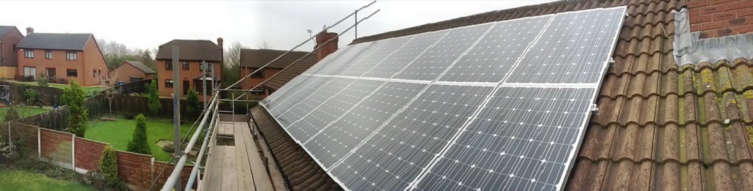
Structural load capacity and roof condition
This is the first true gate. A commercial array adds dead load to the roof and, on a flat roof with ballasted or attached racking, changes how wind uplift acts on the structure. Before layout is worth anything, someone has to confirm the existing framing can carry the added weight and resist uplift within code limits. That is a structural assessment, and on most C&I roofs it needs a licensed engineer to sign off.
Roof condition sits right next to load capacity. A roof membrane with five years of service life left is a problem, because pulling a 25-year array to reroof is a cost nobody wants to eat. Designers check membrane age, warranty status, drainage, and the framing type early. The National Fire Protection Association ties electrical safety design to code, and structural and fire requirements ride alongside it.
The National Fire Protection Association describes NFPA 70, the National Electrical Code, as the benchmark for safe electrical design and installation adopted across all 50 states.
NFPA, Understanding NFPA 70 (NEC)
Two numbers drive the decision: the allowable additional load the structure can take, and the load the chosen racking imposes. Ballasted systems avoid roof penetrations but add weight, which can push an older roof past its limit. Attached systems weigh less but require penetrations and a load path into the framing. The racking choice is really a structural choice, and it belongs in this stage, not after the layout is drawn.
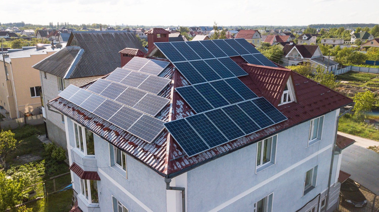
Laying out around HVAC, drains, and setbacks
Commercial roofs are crowded. HVAC units, exhaust fans, skylights, roof drains, satellite dishes, and existing conduit all take space, and each throws a shadow. On top of the physical obstructions, fire code imposes access pathways and setbacks from roof edges and ridges so crews can move during an emergency. Every one of these subtracts from the area you can fill with modules.
The practical move is to map obstructions and required clearances first, then fill what remains. Rooftop equipment casts shade that changes through the day and the year, so a module tucked behind a tall HVAC unit may produce far less than its neighbors. DOE notes that shading and system losses directly cut production, which is why obstruction-aware layout is a production decision and not just a packing exercise (DOE, Solar Performance and Efficiency). A layout that ignores shade inflates the production estimate the whole financial model rests on.
This is where a fast layout tool earns its place. Instead of hand-drawing setbacks and guessing at module fit, PVSketch places an obstruction-aware array and returns an area and production estimate you can trust for the proposal (PVSketch). When the customer asks why the roof only holds 800 kW instead of the round million they pictured, the answer is on the drawing: HVAC, drains, and fire setbacks took the rest.
Conduit runs, equipment pads, and DC-to-AC path
Once the array is placed, the design has to get the power off the roof. That means planning conductor routing from the modules to combiners or inverters, then down to the AC equipment and out to the point of interconnection. On a large flat roof the run length matters, because long DC and AC runs add voltage drop and conductor cost. Where the inverters and switchgear sit, on the roof, on a pad, or in an electrical room, shapes the whole route.
Designers plan the conduit path with penetrations and the structural load path in mind, since every roof penetration is a potential leak and a coordination point with the structural design. The electrical equipment locations also drive the single-line diagram later, so decisions made here echo into the plan set. Voltage drop, conductor ampacity, and overcurrent protection all follow the NEC, and the routing you sketch now becomes the circuits you have to size and label on the construction documents (NFPA 70).
Getting the DC-to-AC path right early avoids a common late surprise: an array and equipment layout that works on paper but forces a conduit run across a fire pathway or through a structural member you cannot penetrate. Route first, then confirm the route respects the same clearances and load path the earlier stages set.
Interconnection and the utility review clock
Interconnection is the gate that runs on someone else's calendar. Before a commercial system can export or offset load, the utility reviews the application to confirm the grid can accept the power at that point of connection. That review can take weeks or months, and on a constrained feeder it can come back requiring expensive upgrades or a smaller system. This is why experienced C&I designers open the interconnection question during site assessment, not after the plan set is done.
The economics behind interconnection are real. Commercial electricity rates and the structure of demand charges shape how much a system is worth to the customer, and those rates vary widely by region and utility (EIA, Electricity prices and factors). A system sized to offset demand charges depends on the utility accepting the interconnection at that size. If review forces a downsize, the financial model changes, and everyone from the developer to the finance partner needs to know before construction documents are drawn.
The commercial solar market keeps growing, and interconnection queues have grown with it, which is part of why timelines stretch (SEIA, Solar Industry Research Data). Treat the utility application as a parallel track that starts early and runs alongside design, not a step you reach at the end.
Turning the design into a stamped plan set
The deliverable that lets construction start is the permit-ready plan set: a coordinated package of a cover sheet, site plan, array layout with mechanical details, single-line diagram, structural details, placard schedule, and equipment spec sheets. For a commercial project the AHJ reads it as a code-compliance argument, checking it against the NEC and local structural and fire code before issuing a permit. Most C&I roofs also require the structural and electrical sheets to carry a licensed engineer's stamp.
The plan set only holds up if it agrees with itself. The module count on the layout, the string sizing on the single-line, the attachment spacing the structural calc assumes, and the equipment models on the spec sheets all have to match. When those numbers come from separate files drawn by hand, they drift, and a reviewer bounces the set on the mismatch rather than the merits. This is where a coordinated model pays off. PVCAD is an AutoCAD plugin that produces permit-ready electrical and mechanical plan sets, single-line diagrams, and NEC construction documents from one model for projects up to about 5 MW (PVCAD). Because the sheets share that model, an inverter swap or a module count change updates everywhere at once. For teams without in-house stamping, PVComplete's design team delivers plan sets with structural and electrical stamping, which removes the scramble to find a PE at the end of a project.
Commercial rooftop design checklist
Run this before you commit design hours to a C&I roof, and again before the plan set goes out.
- Structural assessment confirms the existing framing can carry added dead load and wind uplift within code, with an engineer engaged for sign-off.
- Roof membrane age, warranty, and drainage checked, so the array is not sitting on a roof due for replacement.
- Racking type (ballasted versus attached) chosen against the structural limit, not after the layout.
- HVAC, skylights, drains, and existing equipment mapped, with fire-access pathways and edge setbacks reserved.
- Shading from rooftop obstructions accounted for in the production estimate the proposal relies on.
- Conduit route and inverter or switchgear location planned with penetrations and voltage drop in mind.
- Interconnection application started early, with available capacity at the point of connection confirmed.
- Plan set sheets agree on module count, string sizing, attachment spacing, and equipment models.
- Required structural and electrical stamps arranged before the set is submitted.
Where C&I rooftop projects stall
Most commercial projects that stall do not fail on the array design. They stall on one of a handful of gating items that got answered too late. The table below maps each phase to its key task and the blocker that most often stops the job there.
| Phase | Key task | Common blocker |
|---|---|---|
| Site assessment | Confirm usable area and constraints | Design starts before obstructions and roof zones are measured |
| Structural | Verify load capacity and roof condition | Existing framing cannot carry the load, or the roof is near replacement |
| Layout | Place array around HVAC and setbacks | Fire pathways and shading shrink the array below the modeled size |
| Electrical routing | Plan conduit and equipment location | Long runs and voltage drop force a rework of inverter placement |
| Interconnection | Get utility to accept the connection | Limited feeder capacity forces a downsize or costly upgrade |
| Plan set | Produce coordinated stamped documents | Sheets disagree, or the required PE stamp is missing at submittal |
The pattern across every row is the same: the blocker is cheapest to solve early and most expensive to solve late. A structural problem found during assessment resizes a proposal. The same problem found after the plan set is drawn scraps a set of construction documents. The fix is to front-load the gating items and to draw the design from one coordinated model so the layout, single-line, and structural sheets cannot drift apart. Fast assessment in PVSketch qualifies the roof, a coordinated model in PVCAD produces the stamped set without sheet-to-sheet mismatches, and PVComplete's stamping service closes the gap for teams that lack an in-house engineer. Keep the utility application running in parallel from day one, and the project moves instead of sitting.
Frequently asked questions
How is commercial solar design different from residential?
Commercial rooftop design deals with far larger arrays on crowded flat roofs, so structural load capacity, obstruction mapping around HVAC, and utility interconnection review carry much more weight than on a home. Production depends heavily on the specific site's shading and losses rather than a nameplate figure (DOE, Solar Performance and Efficiency), and most C&I roofs require a stamped structural and electrical plan set that meets the NEC and local code (NFPA, NEC).
What structural checks does rooftop solar need?
A rooftop array needs a structural assessment confirming the existing framing can carry the added dead load and resist wind uplift within code limits, plus a check of the roof membrane age, warranty, and drainage. The racking choice, ballasted versus attached, is a structural decision because it changes the weight and load path. Because these are code-driven safety items, most commercial roofs require a licensed engineer to sign off (NFPA, NEC).
Why does commercial solar interconnection take so long?
The utility has to review the application and confirm the grid can accept the power at that point of connection, and on a constrained feeder that review can require upgrades or a smaller system. As the commercial market has grown, interconnection queues have grown with it (SEIA, Solar Industry Research Data). Start the application during site assessment and run it in parallel with design so it does not become the last gate.
What goes into a commercial solar plan set?
A commercial plan set includes a cover sheet, site plan, array layout with mechanical details, a single-line diagram, structural details, a placard schedule, and equipment spec sheets, all coordinated so the numbers agree. It must comply with the NEC (NFPA 70) and local structural and fire code (NFPA 70). PVCAD produces permit-ready electrical and mechanical sets from one model for projects up to about 5 MW (PVCAD).
How do you estimate how many panels fit on a commercial roof?
Start from the roof footprint, then subtract fire-access pathways, edge setbacks, and the space taken by HVAC, drains, skylights, and existing equipment, and account for the shade those obstructions cast. Shading and losses directly reduce production, so an obstruction-aware layout is what makes the estimate reliable (DOE, Solar Performance and Efficiency). PVSketch produces a fast obstruction-aware layout with an area and production estimate for the proposal stage (PVSketch).
Can PVComplete stamp commercial solar plans?
Yes. PVComplete's design team delivers permit-ready plan sets with both structural and electrical stamping, which helps teams that do not have a licensed engineer in-house (PVComplete). The plan sets themselves are produced in PVCAD as NEC-compliant electrical and mechanical documents for projects up to about 5 MW (PVCAD).
Sources
- NFPA - Understanding NFPA 70 (NEC)
- NFPA 70 (NEC) product page
- DOE - Solar Performance and Efficiency
- DOE - Solar Energy Technologies Office
- EIA - Electricity prices and factors affecting prices
- SEIA - Solar Industry Research Data
- PVSketch - Commercial site assessment and layout
- PVCAD - Permit-ready plan sets (PVComplete)
- PVComplete - Design and stamping services